Frequency Difference Keying (Wanjina)
An Experimental Modulation Method - Frequency Difference Keying (FDK)
Firstly, I am sure that this is not a new idea. If it is a new idea, you heard it first here - if not, don't be too unkind!!
Secondly, please don't confuse FDK with DFCW or VFSKCW. That mode was one that I abandoned in favour of FDK a long time ago and which later was brought to practical fruition by Rik Strobbe. It is simply a way of encoding the dots and dashs of CW in a more efficient way. FDK is completely different to that mode.
General Philosophy of FDK: -
The idea for FDK came from looking at many LF signals (some live, but mostly pictures posted to the 'Net) using Spectrogram , a very useful FFT display especially for receiving slow CW. In order to maximise the range of their stations many European stations use slow CW (QRSS) with dot durations sometimes over 10 seconds. Looking at these QRSS pictures, I noticed a couple of things.
Firstly, at poor S/Ns or in the presence of heavy QRN, because the decoding requires some fuzzy logic (deciding if the carrier is there or not), the full benefit of using narrowband reception is not realised. To receive a character using 10 second dot durations you would need in the order of a minute to receive the character. To make sure that the dots and dashes are not blurred, the narrowest FFT BW would be about 0.3Hz. However, if you only needed to detect the presence of a carrier (not dots and dashes) in that minute then you could use an FFT BW of around 0.017Hz (1/60). You can readily detect the presence of carriers as traces on a FFT spectrum display at S/Ns well below the S/N levels needed to visually decode QRSS.
Secondly, for the decoding of the signals a visual display is necessary, ie, an operator needs to be watching the display as no more than about a dozen characters could be displayed at any one time. For slow data rates which might take tens of minutes to pass relevant data, this can be a problem.
These are the reasons for investigating other narrowband methods for LF.
Note: The character duration for FDK has been initially chosen to be one minute per character.
Why Frequency Difference Keying: -
Obviously different characters cannot be encoded by the the presence of a carrier alone. Some unique characteristic needs to be able to be indentified to enable decoding of the characters at the other end.
Some possibilities are:-
- Absolute frequency encoding. Here the characters are indentified
by the frequency of a tone sent. For SSB reception this is difficult
as it would require very high RF frequency accuracy for transmitters
and receivers. This could be minimised by using wide frequency spacings
between different encoded characters but would still require sending
of a reference tone to establish the position of the tones. The required
reference could be eliminated by using AM modulation. The demodulated
tone frequencies are in this case independant from relative offsets
(within reason) between the transmitted and received RF signals. However,
AM suffers from a rapid falling off of the output to input S/N at low
S/N ratios. This is counter to the goals here.
- Absolute phase encoding. Here the characters are indentified
by the phase of a signal frequency tone sent. Would require sending
of a reference phase (perhaps 30 seconds reference, 30 seconds character
phase). Not sure about the effectiveness of this method. Maybe later
(much!). A kind of slow two-bit PSK31.
- Frequency difference encoding. The method investigated here.
The characters are encoded as the difference between two tones. A reasonable
mistuning between transmitter and receiver can be tolerated as the information
is encoded in the difference between the two tones sent. The transmitted
signals are similarl to the two- tone PEP SSB test signals so familiar
to amateur operators. Two reception modes are possible:-
- An obvious linear mode where the received audio signal from a receiver in SSB mode is processed by an FFT algorithm and two tones are indentified. The frequency difference is the encoding for each character. This method gives the maximum possible advantage from narrowband reception for FDK.
- A square-law mode where the received audio signal from a receiver
in SSB mode is mixed with itself (producing sum and difference products)
and then processed by the FFT algorithm to find the difference frequency
directly. Mistuning and drift are largely irrelevant here, but it
suffers from the same low S/N dropout as AM above in the paragraph
headed 'Absolute frequency encoding'.
These two modes are described in more detail below.
FDK Transmission Mode:-
When transmitting a character, the difference frequency assigned to that character is calculated (say 5Hz for the space character ' '). Two tones are generated with that frequency difference (5Hz) spaced equally around the centre frequency (nominally 1000Hz), ie, (1000 - 2.5) = 997.5Hz and (1000+2.5)=1002.5Hz - giving a difference of the required 5Hz. Each burst of the tones for each character sent lasts for 60secs and is synchronised with the transmitting PC clock time. The 'channel spacing' for each character has been initially set to 0.1Hz. A beacon mode is provided for repeating a set message if necessary.
FDK Reception Mode:-
The receiver synchronises to the receiving PC clock time and acquires data for 47.6 seconds giving a record length of 524288 samples. This is because FFT raw data should have a length which is a power of 2. The nearest block time to one minute using 11025Hz sampling is (524288 / 11025)= 47.6 seconds.
Two modes of analysis of this data are available:-
- Square Law Mode:- Here each sample is multiplied by itself
(squared) before running the FFT. This implements a square law detection
process which produces sums and products. For our space character (frequency
difference = 5Hz) this produces a difference signal at 5Hz (1002.5 -
997.5) and a sum signal at 2000Hz (1002.5 + 997.5). Note that the sum
product will always be 2000Hz for a centre frequency of 1000Hz. The
spectrum is scanned for a maximum between 5Hz and 12Hz. The maximum
is taken to be the signal for the character and is displayed.
The biggest advantage for this mode is that it is immune to both mistuning (within reason - as long as the two tones are in the audio passband obviously) and short term drift. The BIG disadvantage is that it has poor performance at low S/N ratios. This is because the signal presented to the FFT process is the result of the mixing of the received signal with itself. This has implications for output S/N (after multiplying) to input S/N (before multiplying). Assuming a signal with, say, a -3dB S/N ratio. After mixing with itself the resultant output S/N is -6dB. Therefore, compared to the linear process described below, this approach has an output S/N which is only 3dB worse. However, looking at an input signal which has a S/N of -20dB, after mixing, the output S/ N is -40dB, or now 20dB worse than the linear method. So you see at low S/Ns the performance of the square law method falls off rapidly.
Note the above analysis is a rough one and is meant to illustrate relative performance not absolute. Using the square law reception mode I have found that it is roughly equivalent to PSK31 in performance but with a much reduced data rate. The main advantage is that no accurate tuning is required. It is really mostly an academic exercise - but interesting nonetheless. The performance of this mode is greatly improved by filtering the audio before acquiring the data. Using a narrow RF filter or audio output DSP filter of say 200Hz (instead of the normal voice bandwidth) raises the performance by about 6dB or more.
Another disadvantage to this mode is that ANY two signals in the acquired audio passband which produce a substantial difference product in the range of of about 5Hz to 12Hz have the potential to interfere with the decoding process.
- Linear Mode:- Here the audio data is fed straight to the
FFT algorithm. The output spectrum is scanned for the maximum amplitude
frequency and then re-scanned for the next highest amplitude frequency.
These two frequencies are taken to be the two transmitted tones. The
difference frequency between the two tones is calculated and the character
corresponding to that difference is displayed. This method is largely
immune to mistuning (once again within reason - as long as the two tones
are in the audio passband) but is susceptible to drift in frequency
over the one minute acquisition period.
This method requires short-term drift to be less than 0.017Hz over one minute to maintain the S/N advantage and about 0.1Hz over one minute to minimise decoding errors. At LF frequencies of say 190KHz this translates to about 0.1ppm and about 0.5ppm resectively, over one minute. In these days of modern receivers with absolute frequency specs. of +/- 5ppm over a wide temperature range, this is not too tough. Sorry, but narrowband work requires good stability - there is no way around this. Using an FRG-100 with +/-2ppm spec. TCXO and an FT-847 with +/-5ppm spec. plus mixing down from 160m to LF (which makes things worse), I have had no noticeable problems.
Some Notes on the Linear Mode:- Observing the butterfly display of the linear FDK reception mode brings to mind some possibilities:-
- Even with errors rates of 50% or more it is easy to see the symmetrical
spacing of the two tones. Either by manual or automatic means it looks
possible to identify the centre frequency and thereby adjusting the
centre and the range of the scan for the maximums. This would improve
the error rate by eliminating from the scan tones outside the character
tone difference range.
- Following on from above - after indentifying the centre frequency, the error rate could further reduced by doing a SmartScan algorithm. Starting from the strongest tones find the strongest pair which are symmetrically placed around the centre frequency. Kind of like the slow tuning lock found in PSK31.
Test Results:- Ok, so that's the theory, what about the practice? As luck would have it (in this case good luck) there was a very high level of QRN when the first live tests were done.
The pictures below are low-resolution to reduce their size (the FDK screenshots were taken in 1024x768 mode), but hopefully you 'get the picture' :-)
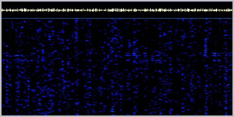
A Spectrogram of the audio with the FDK signal just visible.
Note that while the signal is discernible, trying to use QRSS under these conditions would be well-nigh impossible.
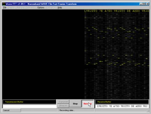
A screenshot of the FDK software in Linear Mode using the same signal as the Spectrogram above.
The butterfly shape can be clearly seen. The center frequency could be easily determined. The error rate is around 6%.
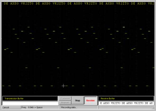
Here is a screenshot of the FDK display in Square Law Mode at a S/N where PSK31 has well-and-truly dropped out.
Here the display only shows the difference frequency as appropriate for the square-law mode. 0% error rate.