0-500kHz Linear Exciter...
Details of a linear signal source covering the frequency range from low audio frequencies to 500kHz.
Introduction
The exciter will essentially provide a linear signal source for the LF/MF range. The linear mode is required to allow experimentation with all signal modes.
The exciter main use will be for generation of a frequency stable linear signal for experiments in the 2200M band (136kHz). A side benefit of the design is that it also provides a highly frequency accurate audio signal for the calibration of soundcards which are commonly used for the generation and decoding of many digital modes.
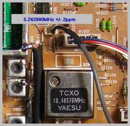
The basis of the exciter is a Yaesu FT840 fitted with +/-2ppm TCXO-4. The standard FT840 circuitry provides a filtered 5.242880MHz reference signal (derived internally from the 10.485760MHz TCXO-4 frequency by a divide-by-two circuit). This fixed frequency signal is brought out externally by adding a flying coaxial cable connection routed through an existing cutout in the FT840 back panel.
Transmit coverage from essentially 0 - 520kHz is achieved by mixing the internal 5.242880MHz reference signal with the transceiver RF output signal tuned over the range of 5.242880MHz to 5.762880MHz.
Another advantage for a linear design is that even for ostensibly non-linear modes, such as CW, the keying shaping of the FT840 is preserved keeping key clicks to designed levels.
Frequency Accuracy and Stability
Unlike some other designs where separate HF frequencies are mixed to provide a low frequency difference signal, this arrangement preserves the +/-2ppm accuracy/stability of the TCXO.
This is due to the fact that any drift in the fixed frequency reference signal will be matched by a proportional drift in the RF output frequency as they are they are both derived from the same +/-2ppm TCXO source. For example, in this design a 1ppm drift in the TCXO-4 reference frequency will cause a 1ppm drift in the RF output frequency. When mixed down to a low frequency difference output signal this frequency will also drift by 1ppm.
Note that this is not the case when using a separate external crystal input to the mixer. In fact, the native ppm stability of that arrangement is lost completely. For example, a HF SSB transceiver with a good 2ppm stability when mixed with a typical 10ppm external crystal of, say, 4MHz, would result in a theoretical best case of 8ppm at 4MHz - which translates to a best case of 240ppm effective stability at 136kHz. Obviously for narrowband experiments requiring accurate frequency setting, this approach is not adequate.
The accuracy/stability of +/-2ppm of the mixer configuration used here translates to better than +/-0.3Hz at 136kHz. However, this is a conservative figure as the +/-2ppm specification for the TCXO-4 is over the range of 0 ~ +50 degrees C. After adjustment of the TCXO-4 to within +/-0.5ppm @ 25 degrees C using Time and Frequency Station signals (I use WWV 10MHz signal which diurnally wobbles about due to ionospheric effects - but usually less than +/-0.2ppm), the operating environment (shack) is usually held within +/-10 degrees C. It is, therefore, be expected that the set frequency at, say, 136kHz will be within +/-(((20/50)*2)+0.5)ppm = +/-1.3ppm. This translates to +/-0.2Hz error with a set frequency at 136kHz. In practice it is expected to be better than that, i.e., within +/-0.1Hz of set frequency around 136kHz.
NOTE: The +/-0.2Hz figure is for accuracy/stability for a set frequency - it is not the frequency resolution. The FT840 has a frequency tuning step (resolution) of 10Hz in SSB mode and so the 136kHz step frequency step is 10Hz. Therefore having set a frequency of, say, 135.940kHz (FT840 dial frequency of 5.378820MHz), the actual frequency will be 135.940kHz +/-0.2Hz and the next available higher set frequency is a 10Hz step up to 135.950kHz +/-0.2Hz.
To set the frequency an external frequency counter is used which has about +/-10ppm stability. The counter calibration is checked and tweaked against the WWV 10MHz on-air signal as conveniently the frequency counter gating circuit reference oscillator is 10MHz and both signals can be seen in the audio in SSB/CW mode in a receiver using ARGO. As the weather warms for summer (and so the mean temperature of the shack rises) the counter reference oscillator will be tweaked so it runs at least with +/-5ppm accuracy. This allows an external frequency coarse "sanity" check of better than 1Hz accuracy. However, the actual quoted frequency will be taken from the +/-2ppm FT840 source specification and calibration (better than +/-0.2Hz).
Mixdown Circuit
The fixed 5.242880MHz reference signal comes out from the FT840 from a part of the circuit which provides a 450mV p-p signal. This signal is simply buffered as I found this level was sufficient to drive the switching diodes in the ubiquitous SBL-1 double balanced mixer. Although this is about -2dBm (the usual LO level into the SBL-1 is +7dBm), this level is sufficient for the low level RF signal (-18dBm) supplied to the other mixer input.
That RF tuneable signal is brought out through the normal FT840 antenna socket. However, the PA is disabled and by-passed by jumpering the cable into the PA to the cable going into the FT840 PA LPF. This arrangement produces a maximum of 80mV p-p across 50 Ohms (-18dBm).
Exciter Output Waveform
The 0 - 500kHz IF product is amplified and filtered to produce a 3.5V p-p exciter output signal. This level should be sufficient to drive a PA to +10dBW to +20dBW.
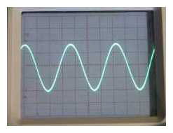
CRO Screen of 3.5V p-p Exciter
Output Signal - 137.640kHz
Construction
Recognising one's limitations can be a liberating experience. While reasonably competent in the Electronic/Electrical areas of expertise, mechanically I am no artist. I actually dislike cutting/drilling metal as I invariably make a botch of it as well as sustaining various injuries requiring first-aid.
Having admitted this shortcoming I have been able to embrace a method of "homebrewing" that pleases me as well as drastically reducing my consumption of band-aids.
In this project I have employed a bread-boarding technique which employs a real breadboard and so harkens back to the origin of the term. It is one of those bamboo breadboards purchased for about $10 from my local foodstore.
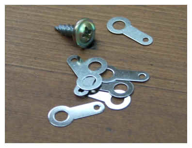
Other mounting components are a supply of solder tags, flat-headed wood screws (self-tapping)....
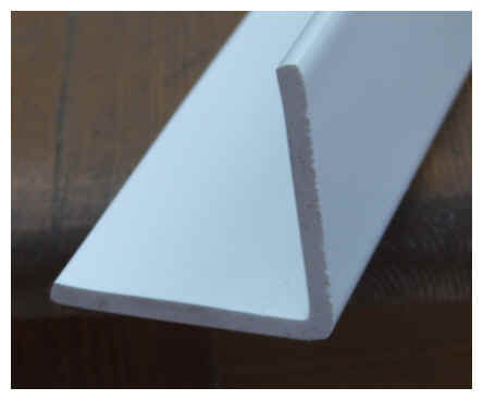
and plastic L-shaped stock....
Tools required are a hacksaw and cordless driver for screws and drilling bamboo/plastic.
Below is the breadboarded and operational 0-500kHz linear down-converter....
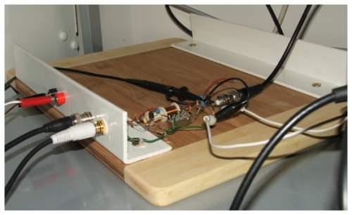
Circuit construction consists of attaching the solder tags in appropriate mounting positions via the wood screws onto the breadboard and then soldering components onto these solder tags. No drilling was required except for the large holes in the plastic L-shaped stock for the input/output connectors. Screwing the plastic L-shaped stock to the bamboo breadboard did not require drilling a pilot hole as the wood screws are self-tappers. The same applies to attaching the solder tags.
The only hacksawing required was for the cutting of the plastic L-shaped stock to length (confession - I actually used a bench-mounted electric circular wood saw).
Here is the construction in more detail...
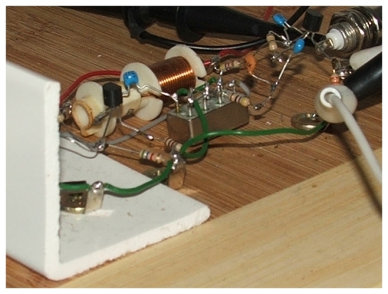
Although this looks like a prototype, I have no intention or desire to tidy it up into a nice box with labels. Apart from the lack of skills on my part, I much prefer the 'naked' look of this construction.
This is probably a remnant of my early radio days working, repairing and modifying valve radios with that lovely point-to-point wiring where you could almost see the electrons flowing around the circuit.