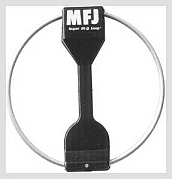
MFJ-1786X Small Magnetic Loop...
About the commercially-made small magnetic loop antenna used at this QTH for the bands 30M to 10M (10MHz to 30MHz).
Background
As mentioned elsewhere I have an aversion to high towers. This probably comes from the experience of watching a 30cm diameter tree in our backyard snapped like a toothpick during a violent wind storm some years back. And I don't like heights - full stop. So all of my LF/MF/HF antennas before the MFJ1786X were wire antennas.
There are some 6-band wire dipoles available, but usually 30M, 15M and sometimes 12M were missing from the coverage. Plus - to get the coverage - most went from the 40M band up. Some required 4:1 or 9:1 baluns.
The block here is fairly densely tree-ed and I observed that with a rotateable dipole the SWR changed as the distance of ends of the dipole to adjacent trees changed as it was rotated. This indicated some coupling and therefore, quite possibly, a degree of shielding in the near field. So what I really needed was a "Steppir-like rotateable magnetic antenna" to reduce the near electric field.
Enter the MFJ-1786X - a small magnetic loop 6-band antenna continuously tuneable from 10MHz to 30MHz (30M to 10M).
Note that it sometimes stated that a magnetic loop has only a magnetic component in the near field. This is not strictly true - there is an intense electric field around the tuning capacitor part of the loop. The difference from a dipole is that the loop's electric field has a small footprint being largely confined to around the tuning capacitor, whereas the dipole has the field between the ends giving a much larger footprint.
Research
I was already familiar in general with characteristics of small magnetic loops and was intrigued by the results obtained by a number of operators with their homebrew versions. I read the reviews of the MFJ-1786 which gave an overall opinion as follows...
Pros- Small size
- Covers 6-bands
- Good for antenna restrictive locations (lofts, ceilings, balconies, etc)
- Low noise on receive
- Seems to work almost as well as a full dipole at the same height
- Reduction in TVI
- Works at low heights when aligned for vertical polarisation
- Expensive
- Narrow bandwidth so requires retuning even for small changes in frequency (several kHz depending on band)
- Quality control could be better - but general opinion was that this was one of the better MFJ products
- Limited to 150W
A big plus for me is the 6-band coverage which, as a bonus, includes the shortwave bands from 10MHz to 30MHz for general SWL. It sure was expensive (RRP US$420 + delivery). The need for retuning was not a problem as I am not a band scanner when operating on the air and in any case on receive the excursion from the tuning point is not as critical (maybe one or two tweaks to cover a band except for 10M). The quality control remarks in the reviews did cause me to hesitate as I had had an issue with the MFJ-969 tuner I bought. For that product I needed to mechanically re-align and lubricate the inductor tuning mechanism to achieve a smooth tuning action. I was worried that if I experienced the same level of quality control on the magnetic loop antenna it would not be so easily remedied.
The power limitation of 150W is not an issue for me - I never intend to get a linear and all my radios except one are 100W or lower.
The manual for the MFJ-1786X Magnetic Loop Antenna can be found here on the MFJ website.
Further Information
The information is split into two sections..
- Operating Observations
- Initial Setting Up
If you are interested in further information from one operator's practical experience - read on.
MFJ-1786X Operating Observations
This section documents the on-air operating experiences of this operator with the MFJ-1786X antenna.
Heads Up
A couple of points to keep in mind..
- After some on air discussions it became apparent that most operators
with experience with magnetic loops as transmitting antennas used them
low to the ground and/or indoors and vertically polarised. Consistent
with my propensity to follow the path less travelled, I have mounted
my loop high (at least for 15M, 12M and 10M) at 7.5m height and with
horizontal polarisation. If you mount this antenna less than 7m above
either ground or a metal roof, follow the MFJ manual advice and orientate
for vertical polarisation.
- You will see many instances where individuals have attempted to homebrew a small magnetic loop and found the performance poor. This is largely due to not understanding the mechanical needs of constructing a working loop. The presence of even a fraction of an ohm of RF resistance will degrade the performance. While not being impressed with the actual build quality of the MFJ loop, at least those requirements are recognised and designed for. The result is the MFJ loop (and other properly designed loops) do work - and work well.
The small magnetic loop is often passed over in favour of more "mainstream" antennas. Those who haven't used a working loop, in the main, tend to think they don't work that well. On the other hand, those who have used a proper working loop love them.
I often think of the small magnetic loop antenna as the "bumble bee" of the antenna world. If you don't know what I mean by this then have a look here.
Summary of DX Performance
Despite the horizontal polarisation and the low height (7.5m) I have been able to work world-wide using 100W SSB.
On the lowest band, 30M, I have worked a VK5 on 100W SSB. Note that in this part of the world the use of SSB is allowed and I have done so - once.
Using JT65A digimode I have worked the world using 25W.
So if you are happy to be able to work the world on 6-bands with an antenna not needing rotation and only occupying a space of 1m radius, then the MFJ-1786X is the antenna for you.
If you want to be the topgun DX-er, it is not for you - except for the following case.
I have noticed some DX-ers use, especially on the higher bands where the directivity of beam antennas is greater, a vertical antenna for omnidirectional receive to monitor a band. When a station is heard they swing the beam in the direction of the station and commence operation on the beam. IMHO, this omni-directional small magnetic loop would be ideal for this purpose when mounted for horizontal polarisation.
Operational Characteristics
Some of the information given here was observed during the initial setting-up phase, but is repeated in the interests of completeness.
Tuning
The need to be tuned within about +/-20kHz (depending on the band) of the operating frequency is largely overcome by the ability to tune on receive noise. Unlike using a conventional ATU on, say a longwire, the noise peak on receive on the magnetic loop is narrow and distinct. In fact, it is a demonstration of a useful side effect of the high Q of the magnetic loop - very sharp pre-selection.
The tuning drifts with temperature. This is most noticeable during the largest change in outside temperature at dusk and dawn. I also have noticed this during a day where there is clear sky and bright sun interrupted by dense cloud patches. As the antenna heats and cools the tuning point swings around by some 50kHz or so. For installations indoors or in roof spaces this would not be so apparent due to the limited rate and range of environmental temperature for the loop.
Receiving Sensitivity
Originally there were some tables and results showing the performance as observed via the RB facility of JT65-HF. I have deleted them as I have decided that they would probably not be of much use, whilst having the potential to aggravate the sensibilities of some individuals.
I have seen remarks to the effect that there is no such thing as a low-noise antenna as outside the near field all characteristics of the antenna (i.e., magnetic or electric dipole) are lost. For 30M the extent of the near field is 5m or so. I am not interested in arguing one way or the other. I just report my observations..
The reference points I have used for receiving sensitivity observations are JT65A and WSPR reports as well as my 4BTV trap vertical. While it could be argued that any antenna would look good against a trap vertical, this point is negated by the strong correlations of those results with the JT65A and WSPR results.
The 4BTV only observations are summarised as follows:-
Comparisons with the 4BTV
- On all bands except 30M the loop is better by an average 6dB
than the 4BTV in terms of JT65A/WSPR S/N reception
- On 30M the loop is on par with the 4BTV - although during daylight hours the loop is better for some reason.
Transmitting Efficiency
Theory says that the efficiency of a small magnetic loop struggles to rival an equivalent ordinary dipole because of low inherent radiation resistance and high relative RF resistance. I have to say I have not seen first-hand evidence of this. I am not interested in the reasons for this. Once again I will just report my observations..
Once again, the reference points I have use for transmitting efficiency observations are JT65A and WSPR reports as well as my 4BTV trap vertical.
The 4BTV only observations are summarised as follows:-
Comparisons with the 4BTV
- On all bands except 30M the loop is on par in terms of JT65A/WSPR
S/N transmission reports
- On 30M the loop is about 3dB down on the 4BTV
Summary
The loop performs much better than I expected. On the lowest band, 30M, the performance is starting to drop - but this is expected due to the low inherent radiation resistance. I would imagine the 40M to 15M MFJ version of this loop (MFJ-1788X) would show a greater drop still on 40M because it has the same loop size as the MFJ-1786X, just with a larger tuning capacitor.
MFJ-1786X Initial Setting Up
This section documents the first experiences by this operator with the MFJ-1786X antenna
This page is fairly long so use the in-page links below to jump to sections of interest.
- Disclaimer
- Pick Up and Unpack
- Inspection
- Initial Testing
- Putting It Up
- SWR Plot
- Tuning Exercise
- First Impressions
- Narrow Tuning Point
- Antenna Tuning Units
- A Simple Vernier Tuning Control
- On The Air
Pickup and Unpack
After some 4 months delay the day arrived to pick up my new MFJ-1786X antenna. The box was bigger than I expected but after a moment's reflection I realised that the 36" (92cm) welded loop could not be broken down for transit. After making sure it was the right model (apparently the 40M to 15M MFJ-1788X model is more popular) I paid the balance and set off home.
The antenna was packed reasonably well - within the bounds of "Fedex-driven dimensional restraints" so often used by US suppliers (if you don't know what that means don't worry about it). No signs of transit damage.
Inspection
My first reaction was that the black plastic cover was bulkier than the 2D picture given on the MFJ website. Then I noticed that contrary to the description on the MFJ website the black plastic cover looked very flimsy. I guess the cover is not meant to be hermetically sealed and so as long as it keeps the dust and rain off it will do the job. Time will tell. There were no practical issues in the reviews I read in terms of the cover - only a less than favourable impression of the look of it. My reaction was the same.
After unpacking all the bits and perusing the parts list I noticed that the four bolts used for the vertical polarisation mounting arrangement were missing. The four self-tapping screws for the saddle fixture used for horizontal polarisation mounting arrangement were also missing. The four missing bolts for vertical polarisation would probably be difficult to obtain from the hardware store, but the missing self-tappers for horizontal polarisation could easily be sourced from my parts bin. I had been equivocating between vertical and horizontal polarisation configurations - now that decision was made for me - I would be using horizontal polarisation. Thanks MFJ Quality Control !!!!

The next thing that gave me concern was that the 12V power supply for 240V had no mains plug - just flying leads. So a trip to the hardware store for a mains plug would have been necessary except for having a suitable plug pack from the junk box (ex-Amstrad PPC640 power supply). After checking that the output was floating with respect to ground I was pleased to see that the output plug on the plug pack was the correct size - some days you win.
NOTE: Do not just rely on the fact a power supply has two pins on the mains plug to determine whether a plug pack is ungrounded - check it with a meter to ensure there is no voltage between the output and ground. Diiferent countries have different standards - know yours !!! I have "floating" plug packs that will give you a tickle if you hold an output pin and touch ground. Of course there will always be some voltage due to coupling across interwinding capacitance of plug packs - but some are substantially higher than others. I have one brand of "floating" plug pack that shows 90V of 50Hz between the output and ground unloaded.
WARNING: This warning appears many times in the MFJ-1786X Manual so I guess it is important !!!
Do NOT use a grounded supply for the control head. If you don't know how to test that a supply is ungrounded either find someone who does or use the supplied power supply wired up by someone with electrician grade qualifications. Severe damage will result to the control head and/or the tuning electrics if you muck this up.
This is because the control head places a DC drive voltage for the tuning motor in the antenna head across the antenna coaxial cable. For reverse direction it reverses the voltage. If the power supply you use is grounded it will be shorted out through the control head to ground in either the "up" or "down" drive modes. This will damage the control head.
Initial Testing
After connecting up for initial testing and familiarisation on the shack floor as per the MFJ manual, I was pleased to hear the tuning motor in the antenna head whirring away. The operation of the coarse and fine tune buttons was verified as well as the limit switches. Using an MFJ-259B antenna analyser I could see a dip in SWR when the antenna was tuned up and down. Standing up against a wooden bookcase the minimum SWR on all bands was about 4:1 - not surprising given the metal racks and rebar in close proximity. Adding the horizontal polarisation mounting bracket made this rise to 5:1, but this was not a worry at this stage. Touching the part of the loop where the tuning capacitor bridges the gap showed how easily the loop was detuned (SWR > 25:1).
NOTE: Do not ever touch this or any magnetic loop when power is applied - RF burns are particularly nasty as they are not just skin deep....
At this point I noticed the plastic cover cutouts around the radiating element tubing were not sufficient to prevent the platic cover coming in contact with the element at these same sensitive points. As the parts of the loop connecting to the tuning capacitor are high voltage points (even at low powers) it concerned me that during wet weather there would be a leakage path across the cover. Add some dust, gunge and bird droppings over time and I suspect there may be evidence of variation in SWR under different moisture conditions. As the cover is fairly thin I was able to nibble away at the cutouts with a small set of sidecutters and provide about 3mm clearance where before there was none. I am under no illusions that given exposure to the elements over time that there won't be some warping of the thin cover material, perhaps causing it to contact the tuning element again - but at least not from the get-go.
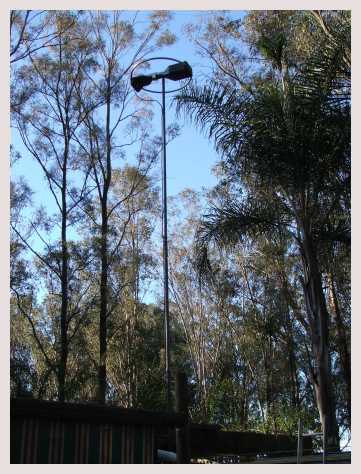
Putting It Up
I already had one of those TV push up masts which carried the aforementioned triband rotateable dipole (and a dualband 2M/70cm vertical). This would now be given over to the MFJ-1786X. The tuning motor in the antenna head on the mast obtains its power via the RF coaxial cable connection. Therefore it was simply a matter of taking down the mast, removing the two existing antennas, attaching the MFJ-1786X in the horizontal configuration and connecting the existing RG-213 coaxial cable run. The mast is attached to a wooden pergola with a partial iron roof next to an iron garden shed. Surprisingly the an initial test run with the antenna about 1m above the iron roofs level showed SWR could be dipped across the whole tuning range to less than 3:1.
This was encouraging as such a setup is a stated no-no for horizontal polarisation installations. Raising the level to 3m above the iron roofs resulted in minimum SWRs of less than 1.5:1 for all bands. Finally, raising the antenna to the full 7.5m height (about 5.5m above the iron roofs) resulted in minimum SWRs of less than 1.3:1 for all bands. MFJ-259B antenna analyser readings are tabulated below.
Minimum SWR Vs Frequency for Horizontal Polarisation @ 7.5m Height
|
Frequency (MHz) |
Minimum SWR (as per MFJ-259B) |
|
29.600 |
1.0 |
|
28.450 |
1.2 |
|
28.000 |
1.3 |
|
24.930 |
1.3 |
|
21.450 |
1.2 |
|
18.150 |
1.3 |
|
14.150 |
1.0 |
|
10.140 |
1.0 |
As you can see the loop can be adjusted for a low SWR on all 6-bands
SWR Plot
The MFJ-269B antenna analyser was set to frequencies from 10MHz to 30MHz in 1MHz steps and the MFJ-1786X antenna was tuned for minimum SWR and recorded. At each 1MHz step the 2:1 SWR bandwidth was measured as shown below.
The blue curve is the SWR and the purple curve is the 2:1 SWR bandwidth in kHz. The approximate position of the six amateur bands covered is shown at the bottom of the graphic.
Note the coarse frequency steps are 1MHz and that the curves are smooth interpolations - finer steps would probably show slightly different curve shapes.
Subsequent checks at 500kHz steps showed a maximum of 1.6:1. All parts of the amateur bands between 10MHz and 30MHz show a SWR reading of less than 1.3:1 in band.
A few things to note. The 2:1 "SWR bandwidth" (purple curve) increases in absolute terms as frequency increases. This curve rises faster than the fractional bandwidth which seems to indicate that the Q drops as frequency increases.
Note also that although the 2:1 SWR bandwidth curve rises steadily, it goes against the trend at two points (23Mhz and 27MHz). This is to be expected as these frequencies coincide with peaks in the SWR curve. Logically if the starting SWR is closer to 2:1 then the SWR will hit 2:1 faster as the measurement frequency is varied around the tuned frequency - effectively lowering the 2:1 SWR bandwidth.
It occurs to me that on 30M the 2:1 SWR bandwidth is getting close to an SSB channel bandwidth. By the time we are tuning to 20M the 2:1 SWR bandwidth is about 9kHz. I wonder whether the users of the 40M to 15M version of this loop have found issues when operating on 40M SSB....
Another point to ponder - when the loop was left tuned to a frequency (say the 15M band) sweeping the MFJ-259B antenna analyser up and down the frequency 10MHz to 30MHz shows the the impedance dropping to a few ohms at frequencies spaced 4MHz apart. In the first instance I observed that this followed the same pattern as the dips and peaks in SWR in the graphic above - i.e., spaced 4MHz apart.
Further more - setting the MFJ-259B to 15M and sweeping the tuning of the loop over its full range showed the impedance dropping to a few ohms. Similarly for the 12M and 10M bands, the impedance of the loop as measured by the antenna analyser drops to a low value when the loop is mis-tuned. However, for the bands 17M, 20M and 30M, the off-tune impedance remains high.
Consequently, I will not be relying on the Hi-SWR protection circuits of my solid-state radio during tuning. Tuning will be done at low powers. I know lots of operators tune mobile whips via indicated power out without disasters, relying on the protection circuits to handle the off-tune mismatch. I am not that brave.
Initially I am using a TS520S for transmit tuning exercises. As that radio doesn't have WARC bands this is a temporary setup until I am comfortable enough with the tuning process to attach my FT-847, which has a front panel knob for RF power level.
Tuning Exercise
The above measurement exercises was good practice for tuning skills. I find my operating characteristics do not suffer from the nuisance of tuning that others report, probably due to the following reasons.
- for receiving, the usable bandwidth is much wider than the 2:1 bandwidth given above.
- the actual tuning procedure is straightforward. I would much rather tune the MFJ-1786X with up/down buttons than twiddle the three interacting knobs of a conventional antenna tuner that would be needed for a broadband dipole.
- I tend to either call CQ myself on a clear frequency and don't tend to be a hunt and pounce operator.
First Impressions
These are subjective impressions - not proper measurements.Receiving
Connecting the MFJ-1786X to my TS520S boat anchor verified the comments that if the loop is not tuned close to the receiving frequency you will hear NOTHING !!! My initial reaction to this characteristic was two-fold.
First - this means the loop performs as a high Q front end preselector which should improve performance with respect to intermodulation. You can't get more "front-endy" than tuning at the antenna head.
Second - I like tuning things. Peaking for maximums is a connection to the physics of the magic of radio for me. Playing around with tuning verified the comments in the reviews that initial coarse tuning can be done using the induced noise from the tuning motor in the antenna head. Fine tuning can be done by peaking actual radio noise from the antenna. In the higher bands (12M and 10M), where it is much quieter, this is more difficult to do.
15M Observations
Subjectively I had been monitoring the IBP beacons on 15M for some months now using the triband rotateable dipole (up until the day it was replaced with the loop).
Listening to the beacons on the magnetic loop resulted in reception of the same group of beacons as heard before plus several that I hadn't heard before on the dipole. So, on 15M the loop is subjectively better on receive in terms of S/N than the dipole.
I noticed a change in the characteristic of noise received compared to the dipole on 15M. There was a "crispness" that I have only heard on other antennas out in the country well away from the QRM from electrical gear.
There was an absence of clicks and pops. The noise level was fairly constant, punctuated only by QRN crashes (and IBP beacon CW). The quietness of the antenna is disconcerting. When I changed from a vertical trap antenna to the the tri-band rotateable dipole I saw an improvement in S/N ratios. I am now seeing a further improvement in S/N after changing from the rotateable dipole to the magnetic loop.
Coupled with the fact I could tune to under 1.3:1 SWR on all bands I was beginning to wonder if I had a dummy load....
Transmitting
The first exercise on the transmitting side was to test the "automatic" tuning system. Up until now I had only tuned the loop completely manually - either by peaking on noise or using the MFJ-259B antenna analyser.
The "automatic" tuning function of the control head requires a few watts of RF to provide an indication to the inbuilt SWR crossed-needle meter. Basically the control looks for a dip in SWR after the operator has pressed one of the "Auto Band Select" up/down buttons.
Here there is a gotcha - for the fastest tuning cycle you need to know which side of the transmit frequency the loop is tuned to. You want to set the loop scanning towards the transmit frequency - not away. There is no indication on the control head about where the tuning capacitor is positioned in its range - except when it hits one of the tuning limits. When you are changing bands during continuous operation this is no problem (provided you have a good memeory or make a note) - it is when you start up the next operating day that you will not be sure which way to head off first.
Initially (as mentioned above) I am using a TS520S for transmit tuning exercises. Setting the TS520S to an unoccupied 15M frequency (21.250MHz) in the tune mode I timed how long it takes to tune the loop using the "automatic" tuning mode. Starting from the worse case scenario of 10Mz the tuning process took the following time:-
- Control head time to "automatically" find SWR dip at 21.250MHz starting from 10MHz lower limit = 25 seconds
- Time taken to manually trim SWR to minimum using "Fine Tune" buttons = 7 seconds
Total time 32 seconds (worse case to 15M).
Obviously if you were hunting for 10M band you would pre-position the tuning to the upper limit 30MHz before hitting the "Auto Band Select" down button. Most tuning sequences would be less than this, especially if you have an on air signal to tune to in receive mode first.
Now all I need is some sunspots to see how the loop performs on transmit !!!
Narrow Tuning Point
One common thread runs through the reviews (and verified by my own experience) - the SWR dip is NARROW!!!
The MFJ-1786X control head design attempts to address this by providing a set of "Auto Band Select" fast tune up/down buttons and a set of "Fine Tune" slow tune up/down buttons.
Electrically the fast tune buttons cause a constant voltage drive to be supplied to the tuning motor in the antenna head - reversed in polarity for up and down directions. The slow tune buttons cause a pulsed voltage drive to be supplied to the tuning motor - thereby allowing a nudging action to get closer to the SWR dip.
Antenna Tuning Units
To simplify tuning the loop you may be tempted to use an ATU between the radio and the control head.
DO NOT !!!
The loop must be tuned to resonance at the head by the tuning capacitor to load properly.
Attempts to compensate for mistuning at the radio will almost certainly produce conditions that result in poor performance, and at worst, result in damage. This is something that you should be aware of if you have one of those radios with an inbuilt ATU.
The loop operates as a link-coupled device and in common with such devices when the system is not tuned (not coupled) the impedance falls to a low value. This produces a very high SWR on the coaxial cable resulting the usual variation in impedance seen at the input of different cable lengths and/or frequencies.
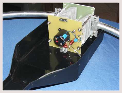
The loop is designed to present a match to the coaxial cable at resonance. The actual impedance at resonance can be adjusted by varying the coupling coefficient between the coupling loop and the main tuned loop. This is done in this design by deforming the coupling from a "tall" oval, through circular, to "fat" oval. The minimum SWR was satisfactory over all bands in my installation so I left the coupling loop shape as it came (on the "tall" side of circular as can be seen in the photo at the top of the page). Some adjustment of the coupling loop may be needed for those installations where there are objects within a couple of meters from the antenna.
It's all in the manual.
A Simple Vernier Tuning Control
After I installed the MFJ-1786X on the mast I had little opportunity to get on the air during the day for a week or so and I got to thinking how I could make some sort of vernier tuning control.
The purpose of such a vernier control would to make it easier to hit the spot of minimum SWR more easily. Because of the narrowness of the SWR minimum it can be a case of a few goes backwards and forwards to get it spot-on. If there was some way to slow down the tuning rate it would make this process, paradoxically, a quicker exercise.
I went through all sorts of ideas - including a separate tuning motor with a small vane to provide some very small tuning effect at the antenna itself. Then I remembered that the power supply specification in the manual allowed for an input voltage range of 9-15V.
The supplied 12V nominal plugpack would probably run at 13-14V. I wondered if there was an inbuilt voltage regulator in the control head to keep a constant drive voltage as the input power supply voltage was varied - turns out there isn't. Using a switchable voltage output plugpack I found that the voltage drive to the tuning motor varied as the input power supply voltage was varied.
Maybe I had found a simple way of applying a "vernier" (i.e., slower) tuning control !!!
Repeating - do NOT use a grounded supply for the control head. If you don't know how to test that a supply is ungrounded find someone who does. Severe damage will result to the control head and/or the tuning electrics if you muck this up.
The results of varying the input voltage setting and timing how long it took to go from one tuning limit to the other are shown below:-
Fast Tune Up/Down Buttons
|
Input Voltage |
15V |
9V |
|
10MHz-30MHz (up) |
31 secs |
90 secs |
|
30MHz-10MHz (down) |
26 secs |
70 secs |
The difference in time taken for opposite directions presumably is
a result of preload in one direction by the backlash spring.
The time taken to tune using the fast tune buttons is roughly 2.5 to 3 times longer at 9V compared to 15V.
Repeating the tuning speed test for the slow tune buttons for the two input voltage levels over a tuning change from 29.7MHz to 28.45MHz gave the following results.
Slow Up/Down Buttons
|
Input Voltage |
15V |
9V |
|
28.45MHz-29.7MHz (up) |
10 secs |
25 secs |
|
29.7MHz-28.45MHz (down) |
6 secs |
17 secs |
Likewise here we see we have about a 2.5:1 to 3:1 vernier action
when running the control head at 9V compared to 15V.
As a result of these measurements I usually use 15V when going between bands and 9V for tuning within a band.
UPDATE: After a period of use I have found I can hit the spot by releasing the button BEFORE minimum SWR and letting it 'coast' into the minimum SWR point. This only came after accumulating a 'feel' for the tuning characteristic. Consequently I always run the tuning head at the nominal 15V these days.
NOTES:
- The above voltage figures are no-load readings of the plugpack - NOT the actual voltage input. The actual loaded voltage will be only a little lower as the variable voltage plugpack used had a current rating of 500mA and the control head draws less than 100mA.
- The "tune rate" versus "voltage" characteristic will depend greatly on the temperature of the environment the antenna is working in. Here at my QTH the range is about -1C to +40C. The antenna tuning motor and lubricated components will be operating within that range (maximum a bit higher than +40C because of the black plastic cover) which is not extreme.
- The drag on the tuning motor appears to vary with the position of the tuning capacitor and therefore the tuning rate also varies between different bands.
- Plugpacks typically are unregulated (the supplied 12V plugpack is unregulated) and so the actual output voltage is specified for a certain current drain. Connecting a typical 15V plugpack to the control head (which draws less than 100mA) will almost certainly result in a voltage greater than 15V being applied - exceeding the specification given in the manual. If you start playing with plugpack voltages make sure you do NOT exceed the maximum specified 15V. That is - RTFM!!!
On The Air - Initial Days
The MFJ-1786X certainly ticks the box for me as far as being a fascinating piece of antenna hardware.
On receive it works better than any other dipole or vertical HF antenna I have had. On 15M I can hear IBP beacons that I have never heard before. Mind you - this is NOT a scientific observation as this could be just a coincidence. Perhaps by luck conditions have finally picked up on the HF bands.
I can say for certain that I am happy with it.
On the transmit side it must be said that magnetic loops are one of the few antennas where the reciprocity principle between receive and transmit performance might not hold. Efficiency drops off fairly rapidly as the loop size gets smaller in turns of wavelength. Not really a problem on receive because as the frequency is lowered the noise level rises anyway. As long as the loop delivers sufficient signal to overcome the receiver front end or preamplifier noise it will work well.
However - on transmit the drop in efficiency directly causes a drop in radiated power.
An extreme example of this is that you can get a 1m square loop to work well on 136kHz receive, but it would be totally useless as a transmit antenna.
Operation over the coming year will determine whether I am as happy with the loop on transmit as I am on receive.
There will be only subjective comparisons made with other antennas as this is always an inexact science unless done on an antenna range.
Rather it will be defined by a "satisfaction" rating.... ;-)
External Links
- Mike Weiler (DB1JAW) has a lot of detail about his experiences with small magnetic loop antennas