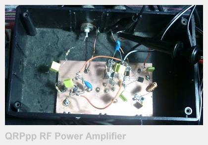
QRPp RF PA for the 630M Band...
Here is a small RF power amplifier based on the design of Roger (G3XBM) which in turn was based on Kyle's (K0LR) LF previous design. It uses a complementary 2N2907/2N2222 switching pair on the output to produce a squarewave with amplitude approximately equal to the power supply rail.
A low pass filter on the output converts the squarewave into a clean sinewave at the fundamental transmit frequency.
The SG1002 DDS source has enough drive to saturate the buffer transistors. However, the output transistors (2N2907/2N2222 pair) didn't appear to be switching correctly. Also the 2N2907 seemed to be getting warm whilst the 2N2222 remained cool.
I could only get 500mW at a 12V power supply level, unlike the approximately 700mW reported by both Kyle and Roger.
Power Increase to 900mW
Initially I could only get 500mW at a 12V power supply level out of the K0LR/G3XBM design, unlike the approximately 700mW reported by both Kyle and Roger.
After putting a CRO on the circuit and looking at the waveforms and DC operating points I made a number of modifications and increased the power supply to 14V which resulted in a power output of around 900mW.
Adjusting the collector-to-base feedback resistors to bias the two buffer transistors into the mid power supply voltage of 6V ensured a 50% duty-cycle waveform thereby maximising the fundamental frequency energy on the output.
The other point I noticed was that the 2N2907 didn't seem to saturate as well as the 2N2222 - and after looking up the data sheet this is explained by the differences in quoted Vcesat voltages (~1V @150mA for the 2N2222 versus ~1.6V for the 2N2907). Placing a finger on the 2N2222 and 2N2907 transistors showed the 2N2222 was running cool whilst the 2N2907 was getting very warm. This is apparently due to the Vcesat specifications being 1.6V for the 2N2907 compared to 1V for the 2N2222 @ 150mA.
To counteract this difference I simply paralleled two 2N2907s which evened up the effective Vcesat voltages by lowering the current through each and made the waveform more symmetrical. Not only did that increase efficiency but also all three output transistors are now running cool.
Power Increase to 1400mW
The modifications I made ended up producing about 1400mW with a 12V power supply and are shown in green in the schematic below...

[Dble-click to view larger size in a new window...]
I also changed the LPF on the output to transform the 50 ohm antenna load to a lower impedance to load the output more heavily while still producing a nice signal waveform...
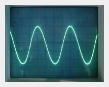
The waveform is a nice clean sinewave when loaded with a 50 ohm resistive load, but more pleasingly, also when loaded with the actual antenna. This is an important point as the antenna only presents 50 ohms resistive at the fundamental whilst presenting a reactive load at other frequencies.
A Small Modification
The original circuit had two buffer/driver transistors. The gain of this arrangement meant that only about 25mV p-p was required to drive the TX to its full output of 1400mW. Inputting more than this caused DC shifts which reduced the output level by shifting the duty-cycle away from the optimum 50%. Setting a 25mV p-p level output from the SG1002 DDS was a tricky business as that miniscule level is right at the bottom of the DDS output level pot slider range and it was difficult to hit the drive-level 'sweetspot'.
I removed the first buffer/driver transistor and fed the output of the SG1002 DDS directly into the second buffer/driver transistor. This produced a smoother setting by virtue of being well up into the output pot range as the circuit now required 1V p-p to get the 1400mW level...
[Dble-click to view larger size in a new window...]
As I said - a small modification - but useful...
BTW - I looked at driving the circuit from the TTL output of the SG1002 DDS instead of the analog sine/triangular/squarewave output and found there seems to be some significant jitter on the output. Presumably because the TTL output is not generated by the fast-clocked look-up table but comes from somewhere else in the digital chain.