Rubidium Frequency Standards...
Details of four Rb standards bought via eBay.
Introduction
I am a bit of a frequency accuracy nut, probably due to my pre-occupation with narrowband modes where knowing where you are in terms of frequency is often the critical factor for success.
Summary
Here are the characteristics of each unit.
|
Serial No. |
+15V req'd |
+5V req'd |
Programmable |
RF Output Connection |
|
41757 * |
Y |
N |
Y - TX on Pin 8 |
DB9 - pin 4 |
|
42370 # |
Y |
N |
N - fixed at 10MHz |
SMA |
|
52970 |
Y |
N |
Y - TX on Pin 7 |
SMA |
|
96634 |
Y |
Y |
N - fixed at 10MHz |
DB9 - pin 7 |
* this unit had to be opened and modified to access the RF output as well as connect to the RS232 control lines. The RF signal was connected to pin 4 of the DB9 connector.
# this unit could be made programmable by opening and adding RS232 connections .
The First Unit
The first of four Rubidium Frequency Standards (S/N 96634) I ordered from two suppliers arrived safely. I ordered three from Supplier #1 and one from Supplier #2. They are all FEI Communications brand, designated FE-5680A - but there are a number of variations under that designator. This first arrival is marked as pre-set to 10MHz and will be used as a general purpose standard if this is the case.
NOTE: This variation of the FE-5680A appears to require two power supplies - a nominal +15V to +18V supply and a +5V supply (an older version..?). Also, as this appears to not to be a "Revision B" version and so reportedly has no user-programmable DDS onboard, it is probably stuck on 10MHz. That's fine as I have a need for a fixed 10MHz source (plus the fact that this was by far the cheapest of the three units).
Digital dividers will be used to provide standard decimations of the 10MHz as far down as 1kHz (for determination of, and the compensation for, soundcard sampling rates).
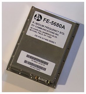
The information supplied with this first unit (S/N 96634) specifies the following pinout for the DB9 connector.
- Pin 1: +15V ~ +18V
- Pin 2: Chassis Ground
- Pin 3: +5V
- Pin 7: RF Out 10MHz Sine
The drift specification for the FE-5680A models is better than 0.0001ppm /day. At the two frequencies of interest in my experiments, 136kHz and 502kHz, this corresponds to 0.0000136Hz and 0.0000502Hz respectively. To see this drift would require FFT data records of about 74000 seconds and 20000 seconds respectively. For comparison, to match this stability specification, the soundcard sampling rate stability would have to be better than about 0.01ppm (assuming 1000Hz audio signal frequency). Not likely.
Assuming the ages of the Rubidium Frequency Standards are about 10 years AND assuming they were accurately calibrated initially, the accuracy should be better than about 0.01 ppm.
The Second Unit
The second of the several Rubidium Frequency Standards I ordered arrived safely from Supplier #1 (S/N 42370). It is also manufactured by FEI Communications, designated FE-5680A - but there are a number of variations under that designator. This second arrival is also marked as pre-set to 10MHz, but is also marked on the case as having a 1pps output.
Note also the SMA connector and supplied lead. As the SMA connector is in a position different to any layout details I can find from the manufacturer's datasheets, I presume that it is a seller modification to make it more useable.
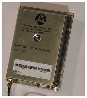
The information supplied with this second unit specifies the following pinout for the DB9 connector.
- Pin 1: +15V ~ +18V
- Pin 2: Chassis Ground
- Pin 7: TX (NOT connected)
- Pin 9: RX (NOT connected)
Unlike the first FE-5680A this needs only one power supply (+15V ~ 18V) and has RS232 input and output connections (pins 7 and 9) which should allow for frequency programming. Another difference is that the signal output (marked as set to 10MHz) is output via an SMA connector as previously mentioned, rather than through the DB9 connector as is the case for the first unit. I am slightly concerned about this as it appears to be a seller modification. I hope the drilling through of what may be a magnetic shield (frequency adjustment is done by varying a magnetic field - Cfield) isn't a problem....
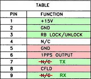
Expected pinout from the manufacturer's datasheet.
Entries in green are the same as the seller's information supplied with the unit. Entries in red may or may not be applicable to this unit and need to be verified.
NOTE: Although this unit is marked with both 10MHz and 1pps, research on the 'net seems to indicate that the '1pps' output has only a period of exactly 1 second when the frequency is set to 223 Hz (8.388608Mhz). According to those sources the '1pps' will have a period of 0.8388608 seconds when the output frequency is set to 10MHz. This should be easy to verify. In any case I have no need for a 1pps output - I use a GPS module to get a 1pps signal which also has the advantage of being in-phase with real time seconds.
Third Unit
The third unit (S/N 41757) of the several Rubidium Frequency Standards I ordered arrived safely (Supplier #2). It is also manufactured by FEI Communications, designated FE-5680A. This third arrival is apparently set to provide a 1pps output only. This probably means it has been factory-set to 223 Hz (8.388608Mhz).
As this unit was used for 1pps only there is no RF output on the DB9 connector, nor is there an SMA connector. Also, there were no RS232 connections on the DB9 connector. I had to open the case to add the connections required myself.
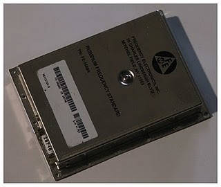
As mentioned in regard to the second unit, I have no need for a 1pps output (I use a GPS module). I just want to use the RF signal and so I had to modify it to gain access to that signal.
This unit (because of the lack of information from the supplier) was harder to press into service than the first two arrivals from Supplier #1.
Powering up showed it was indeed a '1pps' output only on the DB9 connector - no RF output. Wrapping a pickup wire from a receiver around the unit showed a signal on 8.388608MHz, confirming this unit has been set to provide a 1pps signal.
It seems that this unit is the same version as the second unit from Supplier #1, without the SMA RF output connector and the RS232 connections. I am pretty sure now that the second unit from Supplier #1 has been modified to provide those connections by the seller before I received it. This unit, however, is in its raw unmodified state. Time to open the case. This requires removing two screws from the back and front and two screws from the top (one is hidden under the model/serial number sticker). Also the two smaller screws on the side near the RS232 connector need to be removed. Leave the two screws on the bottom untouched. The case needs to be slowly and carefully nudged off square.
As connection information was not forthcoming from the supplier, I used the information from Matthias Bopp's (DD1US) Precision Reference Frequency document to make the modifications. You should read this document to find details not contained here. The mechanical modifications I made are slightly different from both the 'Unit #2-Supplier #1' device and Matthias's modification. Basically I did not do any alteration to the metal enclosure, but instead used the DB9 to bring out all the connections. This involved unscrewing the small board near the RS232 connector (three screws - watch out for the little washers underneath) to gain access to the back of the RS232 connector.
I was careful here - attached to this board is a 3-terminal device thermally coupled to the centre metal bar. I took extreme care as I bent its leads to allow the board to be swung up about 45 degrees.
Fortunately, the legs of the connector are right-angled allowing use of a sidecutter to snip and isolate a number of pins. Although some pins measured O/C (>20MOhm) on a multimeter, inspection of the PCB revealed connections to devices on the PCB for some of these supposedly N/C pins. I chose, therefore, to snip the connection to the PCB for all pins I used.
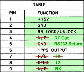
Pinout of the modified FE-5680A.
Blocks in light green are tested functional. Text entries in dark green are the modifications.
Note that for the RS232 TX connection I used pin 8 instead of Pin 7 as the manufacturer does for this function, simply because the snipping of pin 7 would require temporary cutting of other pins already in use.
I ran coax from the RS232 and RF output points as per Matthias's details.
After re-assembling and applying power I now had the factory-set 8.388608MHz signal output at pin 4. Connecting up a laptop and running Hyperterminal (CR/LF) showed the following response to the 'S' command... (9600,8,N,1)
R = 50255055.299544 Hz, F = 2ABB504D47F1AC00
A quick check with the mathematics from Matthias's document showed indeed this corresponds to a frequency setting of 8.388608MHz. As I wanted to line this unit up with the previous units on 10MHz for cross-checking I sent the following command...
F = 32F0AD99
This changed the frequency to 10.000000MHz.
Matthias's excellent document was the key to confident modification of my own unit. I would just make two comments on the information contained therein.
Firstly, I was more comfortable with bringing out the connections via the DB9 connector (after isolating used pins) than working on the metal shield.
Secondly, on my unit at least, the 'RB LOCK/UNLOCK' signal on pin 3 is a digital output (unlock = +4.18V, lock = 0.0V) and I chose not to run a LED to the +15V supply through a 5 - 10k resistor as suggested for fear of damaging the output. For me a shining red LED would indicate an error condition (unlock) and so I use the 'RB LOCK/UNLOCK' signal to drive the base of a transistor buffer through a 1.2k Ohm resistor with the LED in the collector with a series 2.2k Ohm resistor to the +15V supply. On start-up the LED is lit indicating 'unlock' and then goes out when the unit is 'locked'. I am much happier with this circuit and LED behaviour.
First Frequency Check
Fired up one of the Rubidium Frequency Standards (I chose the second of the two units to arrive from Supplier #1, as it only requires one +15V power supply).
Running from 15V the current consumption followed the same pattern as others with these units have found - starting off at about 1.9A and slowly dropping to 0.64A as the heater brings the temperature up to the set point.
Listening on a receiver in CW mode set to 10MHz it was pleasing to hear the frequency swing either side before locking.
Using ARGO set to 120 second dots (nominal 0.01Hz resolution) the display was "calibrated" for a reading of 0.00Hz (the actual audio was around 700Hz). Then the FE-5680A was switched off and the 640th harmonic of the line frequency (15625Hz) of a TV tuned to a station using an atomic frequency standard was displayed. The difference seen was about 0.01Hz. Given the resolution of 0.01Hz this could be an actual difference of 0.001Hz to 0.02Hz. This is a difference at 10MHz of 0.002ppm (2 parts in 109). I am happy with that !!!! This is a 1mHz error at 500kHz and about 270uHz at 136kHz !!!
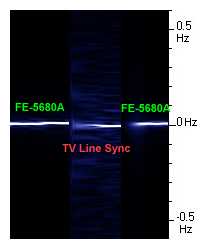
Difference between FE-5680A 10MHz output and
640th harmonic of atomic standard locked TV line frequency
The graphic above shows the difficulty of actually determining the accuracy of these Rubidium Frequency Standards using ordinary equipment. The short-term drift of the receiver (a 5ppm specification FT847) is apparent even after shutting doors to minimise drafts. However, this is close enough for my purposes and the effort of carting the unit somewhere to get it tested against a laboratory standard seems pointless.
Of course it also needs to be appreciated that because the resolution of the DDS that outputs the actual 10MHz signal frequency is only 0.0117Hz - tweaking the Cfield might be necessary to get closer than this at 10MHz - it depends on the actual reference frequency for each unit. Naturally you would need access to a standard which is an order of magnitude better to do this.
NOTE: - tweaking the Cfield for 10MHz only gets you "spot on" for 10MHz - for other frequencies you can still be up to 0.0058Hz out. At this stage, because I won't be running the DDS at frequencies less than 8 to 10MHz the DDS 0.0117Hz resolution will be more than enough.
The next task was to get the dual power supply FE-5680A (+5V and +15V) running to do a comparison.
Lining Up the Ducks
Or checking the first three Rubidium Frequency Standards...
I connected up the remaining Rubidium Frequency Standard (paradoxically the first unit to arrive). I have fired up this one last as it is the version which required a +5V as well as a +15V supply. I added an LM323K +5V fixed regulator running from the +15V supply to provide the power for the FE-5680A digital circuits. Later versions apparently added a +5V regulator internally doing away with the need to provide one externally.
This unit is set to 10MHz and probably can't be changed as it is not a 'Revision B' version.
Checking this unit against the other two Rubidium Frequency Standards and a local TV station atomic clock derived line sync signal (640th harmonic) revealed that all four sources are within the resolution of my receiving setup (0.01Hz @ 10MHz = 0.001ppm).
So now I have three Rubidium Frequency Standards up and running. They might be deployed in the following manner:
- This fixed 10MHz unit (non-'Revision B') as a general 10MHz
standard driving digital dividers to provide a set of useful calibration
frequencies.
- One programmable unit set to 10.485760MHz as the reference source
for the FT840-based Linear Exciter (replacing a 2ppm TCXO).
- One programmable unit set to 10.485760MHz as the reference source for an FRG100 50kHz to 30MHz receiver (also replacing a 2ppm TCXO).
Four of Four...
A fourth RFS (S/N 52970) has been purchased. This unit has an identical configuration to the second unit received (S/N 42370) and so pictures and details are not repeated here. NOTE: The RS232 connections are wired in (42370 are not)