Tee Vertical Antenna for the 630M Band...
Having used a 'conventional' antenna solution for the 630M for a period of time, I wanted to experiment with a configuration which, while not unique or novel, is at least uncommon.
The 'conventional' configuration was an inverted-L arrangement with the vertical section going up about 13m and then a horizontal top-load wire extending about 8m, the end of which was supported by a tree at about 10m. This was tuned to resonance by a series 800uH tuning coil at about the 3m mark.
I was not satisfied with this arrangement for a number reasons...
- the top-loading wire needed a second support as well as the actual mast
- the high voltage portion of the antenna starting at 3m height was too close to surrounding structures
- tuning for covering the 630M Band was inconveniently done at the antenna
- use of wire elements made the antenna susceptible to breakage from wind and falling branches
- movement of wire elements in high wind caused a swing in impedance producing a varying SWR
- affected by wet weather to some extent
- the 13m height exceeds the 10m limit commonly set by local authorities
So the rough brief for the new configuration is as follows...
- be independent of trees and other secondary supports
- move high voltage portions of the antenna higher up (mid-point)
- coarse tuning to 475kHz and matching to 50 ohms to be done at antenna - fine tuning for band coverage to be done in shack
- use robust hardware store components where possible
- be wet weather tolerant
- height less than 10m
Design
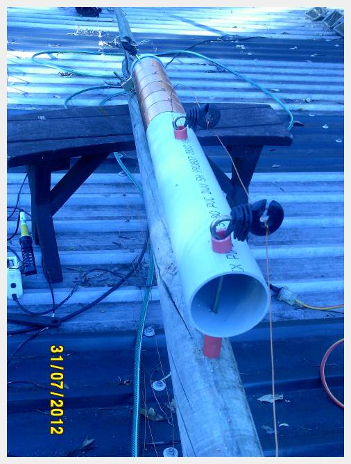
The tuning coil will be mounted at about the 6m level placing high voltage sections well above ground and away from building structures.
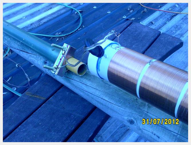
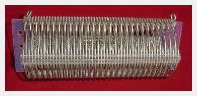
The coil itself is one previously used for 136kHz experiments and has a maximum inductance of 2140 uH. It comprises six sections each wound from 100g rolls of enamelled copper wire.
The 2140uH inductance is expected to be much more than needed according to the modelling done, but it was thought prudent to start with too much inductance and then reduce it as needed.
Easier than going the other way...
Above the coil the antenna extends upwards by another 2.6m to 5m - made variable by the use of a telescopic handle. The bottom 2.6m length of the telescopic handle has a diameter of 36mm. The top half (2.4m long) has a diameter of 28mm.
The plan is to get the vertical resonant on a frequency close to 476kHz by using the required number sections of the coil, going from bottom to top, and then using the adjustable length mast section above the coil to vary the length of the top part to bring the vertical into resonance in the rough middle of the 630M band - 476.5kHz.
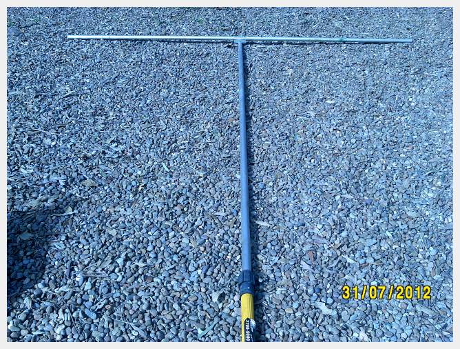
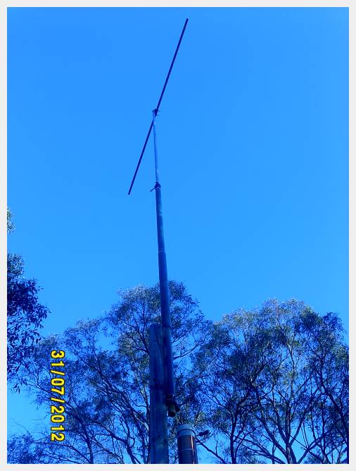
A horizontal section of 31mm diameter aluminium tubing is attached by a TV antenna mast mount clamp at the very top of the pole forming a Tee shape and adding to the capacitance.
This top horizontal section is 2.4m long. The length was chosen as a compromise between the advantage of gaining extra capacitive-loading and the disadvantage of increased wind-loading.
The length of this horizontal section could be increased to about 4m across if it was found there was insufficient capacitance to resonate the vertical 476kHz using all sections of the coil - but this was not expected to be necessary from modelling results.
Initial Measurements
The 'prototype' antenna configuration was raised to do a preliminary measurement of resonance frequency with the full 2140uH coil inductance in circuit and the top section fully extended for maximum capacitance - about 11m high overall...
Using an AA-30 RigExpert Antenna Analyser the resonance frequency was found to be 387kHz with a base impedance of 87 ohms. The base impedance is higher than the previous top-loaded vertical (about 68 ohms), but this was expected as the full coil inductance of 2140uH was used increasing the loss, whereas the previous coil inductance was only about 890uH. Obviously much less than 2140uH will be required to resonate and so the loss should be reduced.
The capacitance above the coil is calculated to be 79pF, therefore approximately 1400uH will be required to bring the vertical to 476kHz resonance. This should drop the coil loss by about 10 ohms compared to the current 2140uH value - making the base impedance about 75 ohms.
Calculations showed that if the top section was left at the fully extended position (11m overall) and the coil was tapped at 1415uH the Tee vertical should be resonant at the required 476kHz frequency.
The tuning coil is made from six sections connected in series for a total inductance of 2140uH. Disconnecting the top section and using the remaining 5 sections gives an inductance of 1585uH - a little higher than the calculated require inductance of 1415uH.
Further calculations showed this 1585uH value should make the vertical resonant on 450kHz. I could do the messy job of finding a mid-coil section winding tap, but I decided to stick with the 5-section 1585uH value and shorten the telescopic section to get to the target resonance frequency.
Disconnecting the top section and using the bottom 5 sections only, raising the antenna back up again showed the vertical was resonant on 452kHz - close enough to the calculated 450kHz to delude myself into believing I actually know what I am doing... ;-)
The next step was to go back to the NEC4WIN95VM modelling software to see how much height would have to be removed to bring the resonance frequency up to 476kHz. This came out to be 980mm. As that would make the overall height just below the 10m maximum height target I was very pleased - theoretically. Down came the antenna again and the telescopic top section was shortened by 1m to make an overall height of 10m.
Impedance Plot - Shack End of 20m Coaxial Cable
[Click to view larger size]
Raising the antenna again and taking an impedance plot at the shack end of the cable showed the vertical was resonant on 478kHz now. This was a little higher than the frequency target of 476.5kHz which I had been using on the old vertical.
NOTE: this impedance plot was done at the end of the 20m coaxial feeder cable and so the fact that the resonance frequency seen there corresponds pretty closely to the actual antenna resonance is due to the antenna base impedance at resonance closely matching the coaxial cable characteristic impedance.
By this time the novelty of lowering and raising the 10m mast had worn off and so I decided to QSY up to around 478kHz for the time being (477.950kHz at the time of writing this). This decision turned out to be fortuitous as will be described next.
Tuning the Band
The purpose of characterising the impedance seen at the shack end of the transmission coaxial cable w.r.t. frequency was to investigate an in-shack tuning arrangement for tuning across the 630M Band.
The resonance frequency as seen at the end of a 20m coaxial feeder cable is 478.1kHz marked by the value of X = 0.
At the lower 630M Band edge (472kHz) the impedance at the end of the 20m coaxial feeder cable was measured to be 38-j105. As the real part of that impedance (38 ohms) is close to 50 ohms, a series inductance could be used to simply cancel out the capacitive reactance and still give a reasonable SWR. The +j105 inductive reactance needed for this was calculated to be 33.7uH @ 472kHz - a value which fits neatly within the range of the air coils I have on hand that have a maximum inductance of about 42uH.
But first, the SWR curve was plotted without a series inductance...
SWR Plot - Shack End of 20m Coaxial Cable
[Click to view larger size]
The air coil was tapped at 33uH and inserted in series which gave the following SWR curve...
SWR Plot With Series 33uH Inductance
[Click to view larger size]
The SWR curve showed a minimum at 472.1kHz which agrees with the expected result from the calculations.
The conclusion to these measurements is that by tuning the Tee Vertical Antenna to resonance at the top of the band, it can be tuned for minimum SWR over the 630M Band, at the shack end of the feeder, by simply inserting a series inductance varied over the range 0uH to 40uH.
The cable loss caused by the high SWR at frequencies within the band away from the antenna resonance frequency are negligible for the 20m cable at these frequencies and are modelled to be less than 1dB.
These measurements were done in dry weather. It will be instructive to redo the measurements in wet weather...
Update - 20 August, 2012
There seemed to be a high level of energy coupled into an adjacent multi-band OCF dipole (80m long), so it was removed. This caused the resonance frequency of the Tee Vertical Antenna to rise by about 6kHz.
After some thought it was decided to re-tune the Tee Vertical 630M antenna to just above the 630M Band (472kHz - 479kHz) and use an in-shack series inductance to tune out the residual capacitive reactance. Calculations showed the loss due to the SWR on the 20m coaxial cable feeder cable to be less than 0.5dB.
After some quick calculations it was estimated that the top part of the Tee Vertical needed to be extended about 150mm to bring the resonance back down to just shy of the top of the 630M Band. The antenna was folded down and the adjustment made and then raised again. The in-shack SWR curve of the Tee Vertical was measured and found to be as follows...
SWR Plot of 630M Band Tee Vertical - Shack End of 20m Coaxial Cable
[Click to view larger size]
...indicating that it is resonant just above the 630M Band as calculated at 479.4kHz.
I intend to use a series 40uH air coil inductance (tapped with a flying crocodile clip) to cancel the residual capacitive reactance seen at the shack end of the coaxial cable feeder over the 630M Band. A quick check of the SWR curve with the full 40uH inductance in circuit showed the following results...

SWR Plot with 40uH Series Inductance - Shack End of 20m Coaxial Cable
[Click to view larger size]
...with a minimum SWR at 471.5kHz indicating that the 40uH coil is sufficient to operate across the 630M Band (472kHz - 479kHz).
Wooden Support Tower
The support structure for the Tee Vertical antenna is a wooden tower attached to the side of a screened outdoor room. It is constructed with 5 round treated pine logs.
The base is a 600mm length of 75mm diameter pine log buried in a cement footing and protuding 150mm above the ground. Bolted to each side via a threaded rod are two 3.6m lengths of 100mm diameter pine log which are, in turn bolted to a beam at the roof line of the screened room.
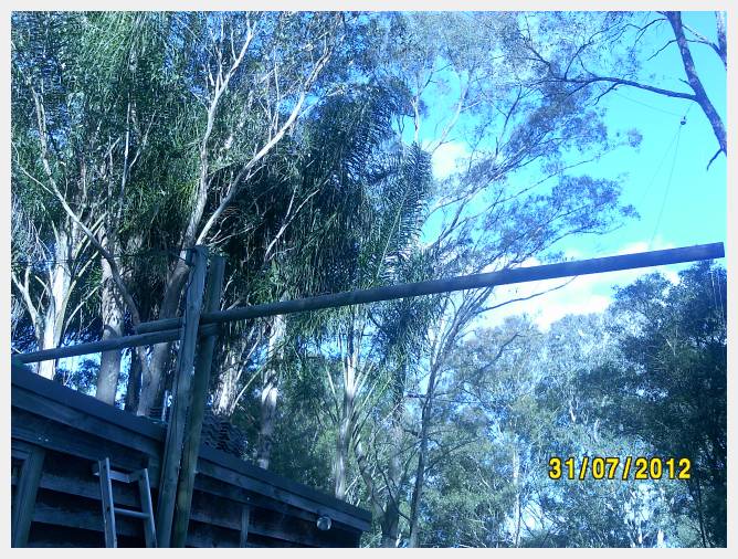
Wooden Support Tower - Folded Over
[Click to view larger size]
At the top of these two beams, and in between, is fastened a single 3.6m length of 75mm diameter pine log. The two securing threaded rods are separated by approximately 500m vertically. Removing the top threaded rod allows this top section to be folded over by pivoting on the bottom threaded rod onto the screened room roof - conveniently flat.
In the above picture the top 3.6m mast section is lying horizontally on the roof to the left. Also attached to the pivot point (extending to the right horizontally in the above picture) is a 3.6m length 75mm diameter pine log whose primary purpose is to acting as a counterweight when the antenna is lowered or raised - but also stops the antenna folding over in a direction away from the screened room.
The maximum support height is 6.6m at which point, in the current configuration, the tuning coil and upper telescopic section are attached.
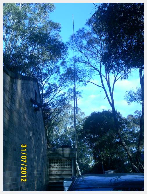
Wooden Support Tower - Up Supporting Tee Vertical
[Click to view larger size]
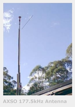
This wooden tower has been in service for about 12 years now and was originally built to carry an LF antenna for my experiments with my Scientific Assigned Licence for 177.5kHz (AXSO) circa 1999 as shown by a photo from my archives.
It has held up very well in the heat, wind and rain. Perhaps I should renew the top most part as it is as riddled as a pincushion with various screw holes from numerous antenna configurations it has supported over the years (Hustler 4BTV, rotateable dipoles, VHF/UHF discones and whips..).